Introduction
Transformer tank vibration mainly originates from the core and windings vibration, and they can be easily acquired. Therefore, the vibroacoustic signals of a transformer tank are widely adopted to monitor the conditions of core and windings due to the internal mechanical condition decides the generation and transmission process of vibrations inside the power transformer.
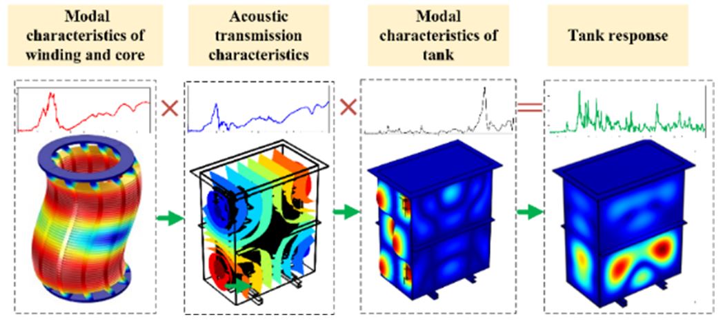
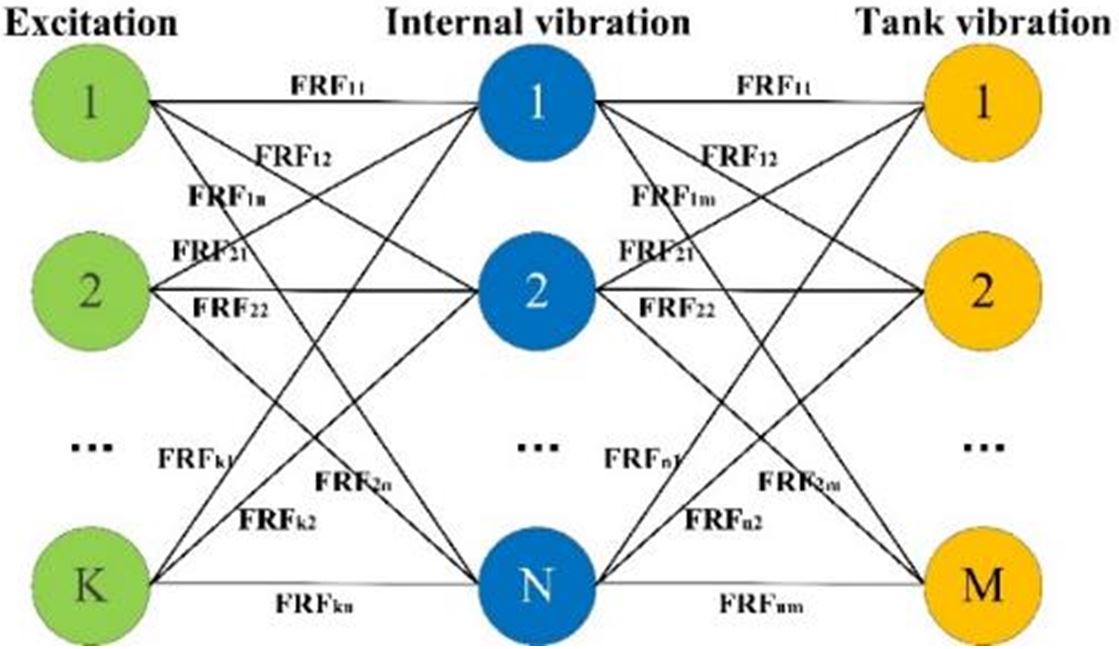
Internal vibrations transmit through transformer oil (oil-borne vibration) and solid structure (structure-borne vibration) to the tank. The modal characteristics of the core, windings and the tank work as a series-connected filters to modify the excitation, as shown in Fig.1. A mathematical way to describe the relationship between the excitation, the internal vibration and tank responses is using FRFs to illustrate the correlation between the excitation and responses, as Fig.2 shows. The excitation type can be electromagnetic forces acting on windings and the magnetostriction of the iron core. The FRFs represent the response between excitation and internal vibration as well as the response in different transmission paths between the vibration sources and the tank. Hence, to understand the tank vibration characteristics, modal characteristics of windings and the tank need to be investigated.
Modal characteristics of windings
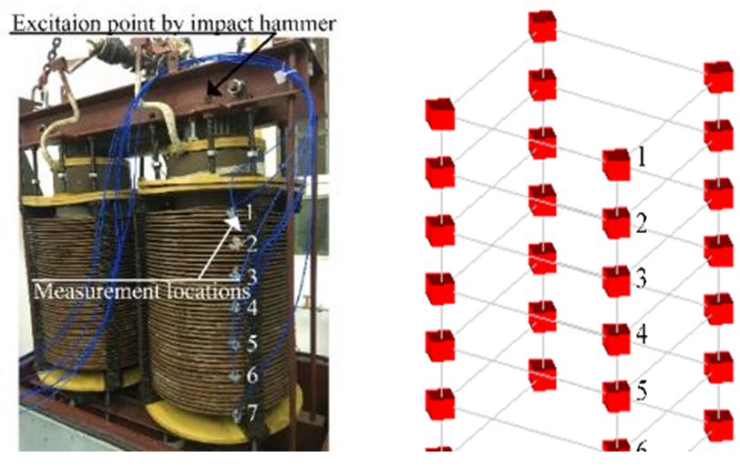
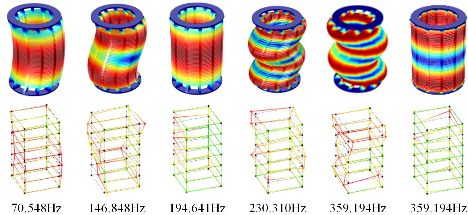
EMA was carried out on the 10kV winding. The location of the excited force point and measurement locations are shown in Fig. 3. The obtained mode shapes in EMA is shown in Fig.4.
Characterization of internal vibration sources
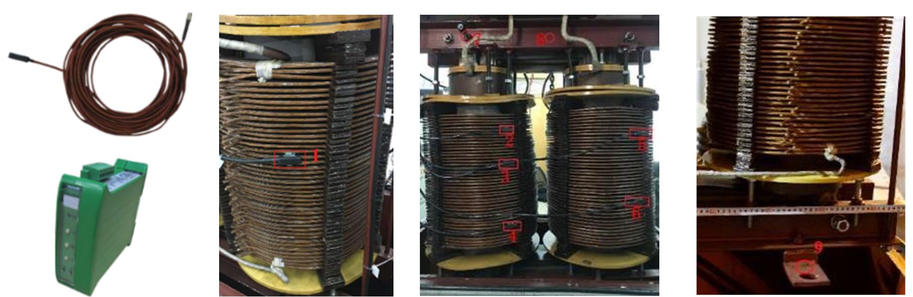
The optical accelerometer and measurement points are shown in Fig.5. Optical accelerometers EVA1106A were attached to the 10kV winding in the axial direction. MP1, MP2, MP3, MP4 locate at the 10kV winding on the left core limb with MP2, MP3, MP4 on the front side and MP1 on the backside. Another two EVA1106A were attached to MP5, MP6 of the winding on the right core limb. Piezoelectric accelerometers PCB601C01 were attached to MP 7 and MP 8 on the clamping frame of upper yoke and MP9 on the foot-pad to detect the normal vibration of the structure surface.
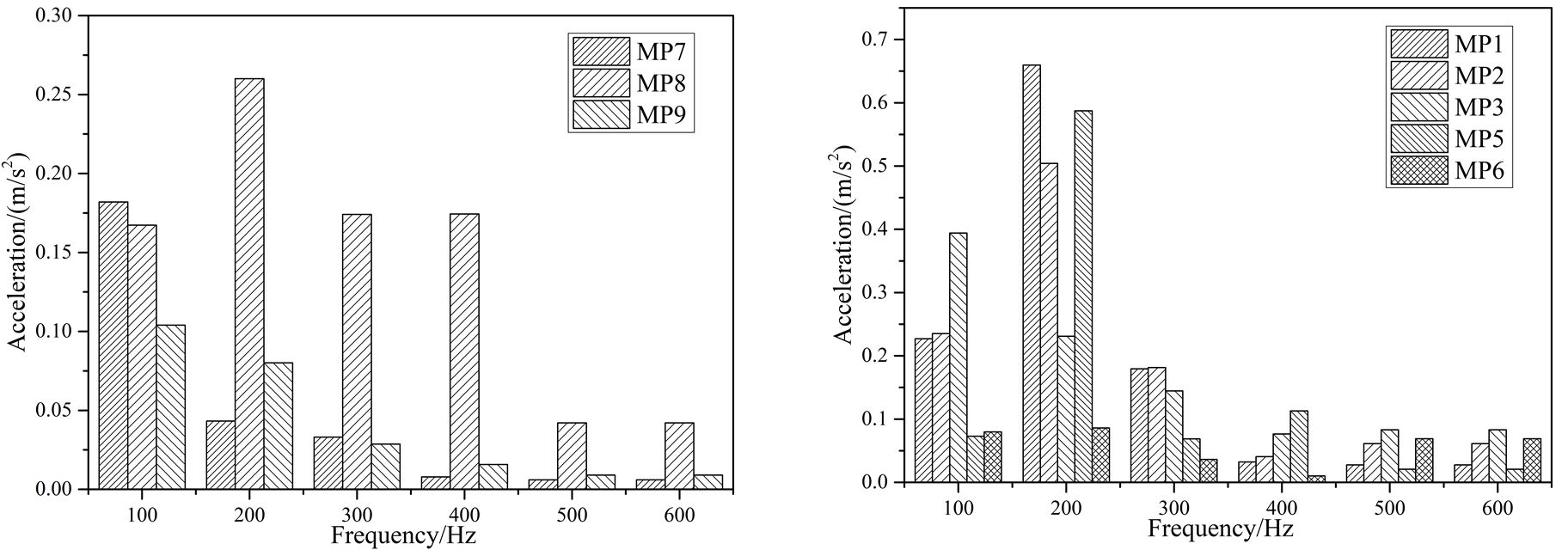
Winding accelerations in the no-load test are shown in Fig. 6. The strong 200Hz acceleration is due to the 200Hz of core vibration gets close to the natural frequency 194.641Hz of winding and results in the resonance.
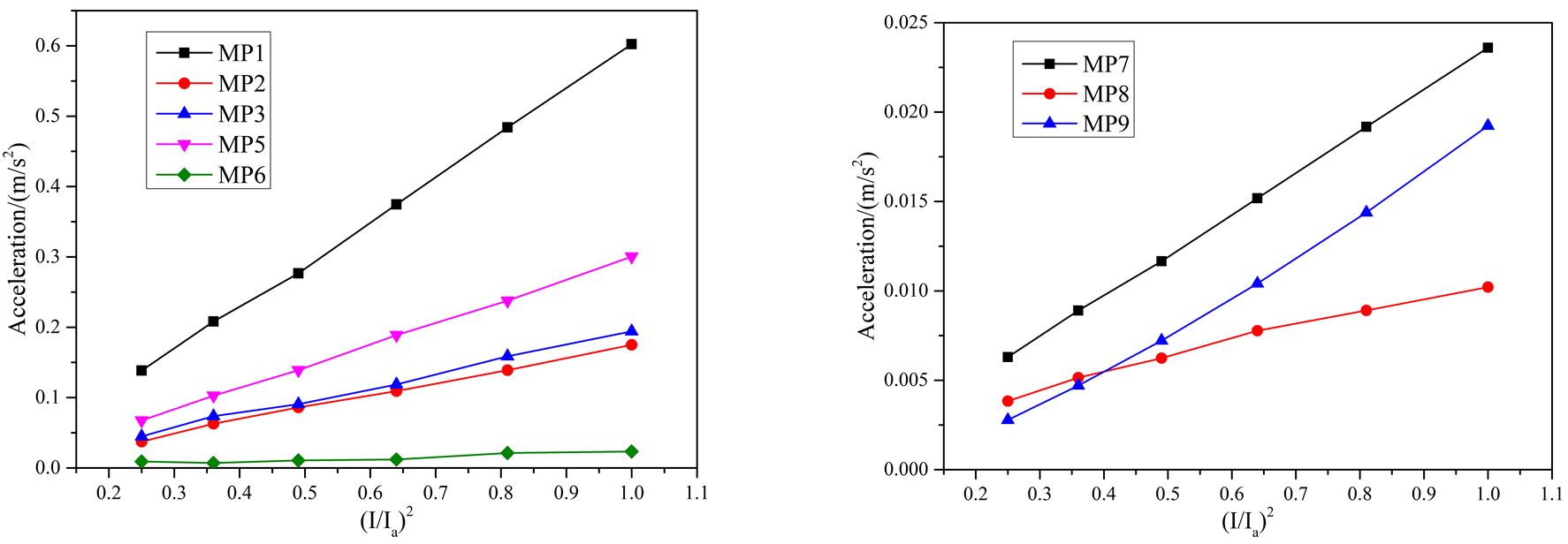
The relationship between accelerations of measurement points and current square is shown in Fig.7. The acceleration follows the linear relationship with the current square. But, its amplitude at different measurement points is affected by the winding modal characteristics and varies a lot. The acceleration of MP1 is larger than that of MP3, although MP1 and MP3 locate on the same winding disk. The accelerations of the core and the frame are lower than that of winding.
Modal characteristics of the oil-filled tank
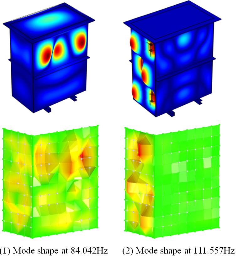
The EMA mode shapes at 84.042Hz and 111.557Hz of the oil-filled tank are shown in Fig.8. The thin plate structure brings the respiratory mode shapes to the tank. At 84.042Hz, the deflection mainly concentrates on the front surface of the tank. The upper part of the front surface shows a one-three order mode shape in the width direction. The asymmetry deflection in the height direction is caused by the static pressure on the tank wall. Being proportional to the depth of liquid, the static pressure acting on the lower part of the tank is larger than that on the upper part, which brings different constant deflection on the tank. As a result, the mode shape in height direction is asymmetry. However, the influence of static pressure on the side surface is not obvious. The mode shape at 111.557Hz of the side surface shows a symmetry two-three order mode shape.
Influence of the tank’s modal characteristics on received winding vibration
In the oil-borne transmission experiment, the internal structure was slung up by a crane to ensure that it had no mechanical contact with the tank bottom. In this suspension condition, the FRFs between excitation point on the top clamping screw and measurement points on tank were acquired. The excitation point and measurement points on the front surface of tank are shown in Fig.9(1). FRFs on winding and tank under mechanical impact excitation is shown in Fig.9(2). Compared with the FRFs on winding, the FRFs on tank have more resonant peaks. The resonances of tank at 194.641Hz and 230.310 Hz come from the winding resonance. While the resonance at about 112Hz and the separated resonant peaks between 400Hz and 1000Hz are affected by acoustic propagation and tank response characteristics. The FRFs on winding and tank are in the same order of amplitude, showing that transformer oil has a strong ability to transmit internal vibration to tank.

Conclusion
- Winding vibration is strongly coupled with core vibration, but the core is seldom affected by the winding vibration. Under the excitation from core vibration and influenced by its modal characteristics, winding also vibrates at frequencies other than 100Hz, which is different from previous cognition that winding mainly vibrates at 100Hz.
- Modal characteristics of tank has a significant influence on changing the winding modes and vibration patterns.